B18B/B20 Valve Cover Venting
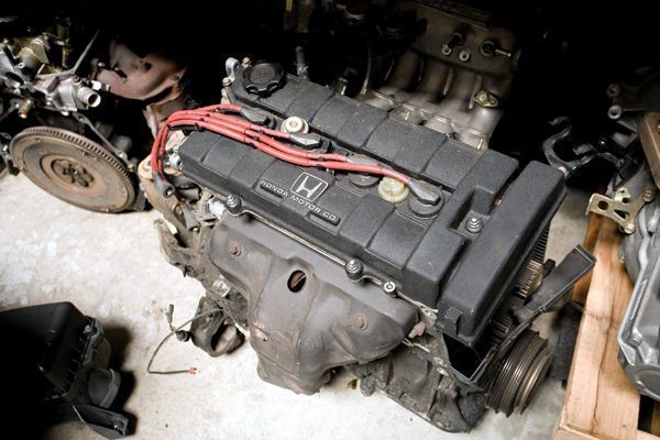
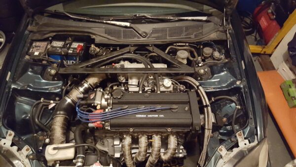
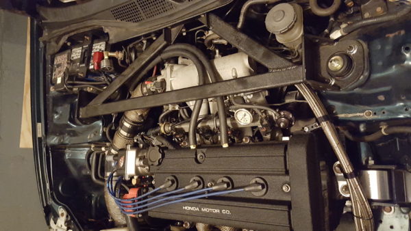
In this project we document the process to properly vent your Honda B18B or B20B/Z engine through the valve cover for vented catch can applications.
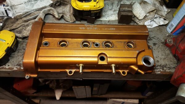
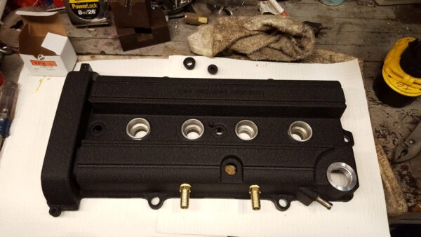
Our process does not require welding and is perfectly suited for a driveway project. The installed ports can be used for -10AN lines as well as 1/2" automotive oil line hose.
Crank Ventilation Explained
All Honda's factory built within at least the last 30 years use the "traditional" PCV system for dealing with crank case vapors and pressures. Blow-by mixed with fuel that leaks past the piston rings on the compression stroke and oil spray are recycled back into the intake manifold and burned up on the power stroke for green and EPA purposes.
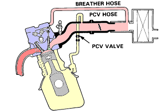
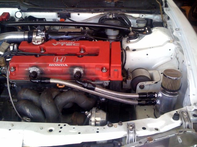
The traditional PCV system uses the engine vacuum to suck the crank case vapors and recycle the gasses back through the combustion cycle. While this process keeps our streets clean, the added mixture can lead to valve deposits and pre-ignition. In line catch cans or air/oil separators allow oil vapors to be further scavenged but can never be 100% effective.
Like classic muscle car motors of the past, most high performance engines vent crankcase vapors to atmosphere to avoid the negative effects of venting using the "traditional" PCV system. But due to the lack of vacuum and increased crankcase pressures from a high performance engine the original ventilation hoses and ports are usually not adequate for vacuum-less crankcase venting.
B18B/B20 OEM Crank Case Venting Design
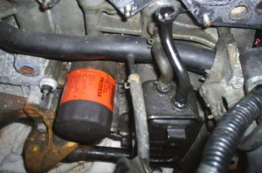
OBD1 B18B engines utilized the black box on the back of the block to vent the crank case. OBD1 B18B valve covers are not tall enough to fit the required fittings without welding and special baffle fabrication.
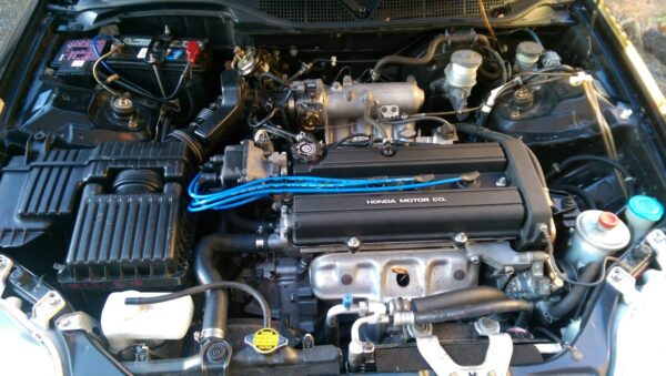
Honda eliminated the black box in OBD2 B18B and B20 engines by venting the crank case through the valve cover. This design change effectively increased the valve cover height.
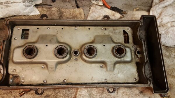
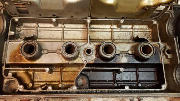
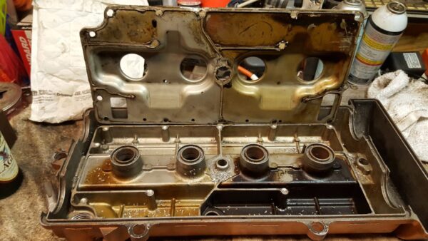
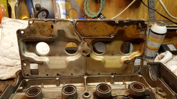
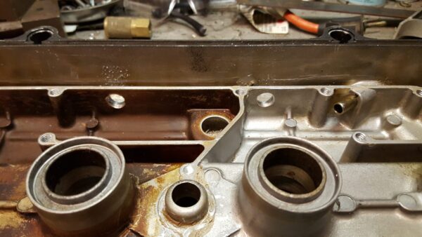
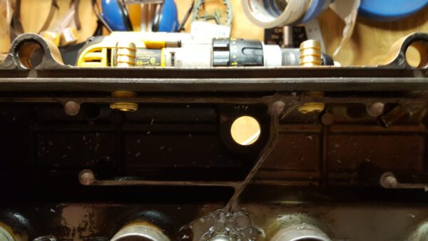
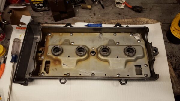
To ensure proper air flow Honda partitioned the valve cover into two sections using cast baffles and a riveted baffle plate. Creating a fresh air section and crank case vapor evacuation section.
Riveted Baffle Plate Removal
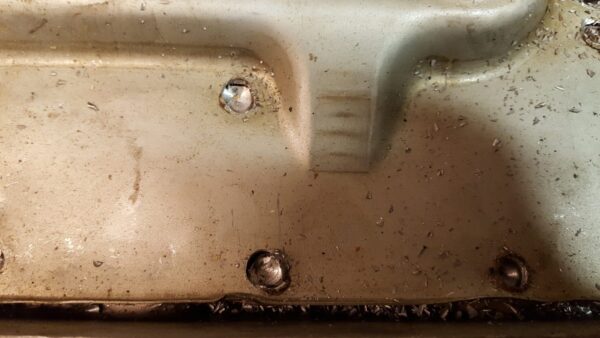
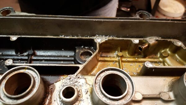
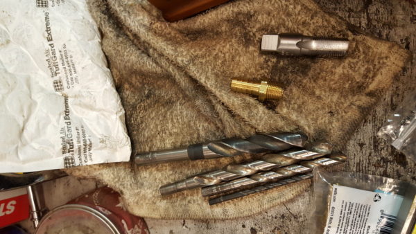
1. Using 1/8" drill bit locate and drill out all 17 rivets. Center punch all rivets to keep drill bit from walking.
NOTE: Only drill enough to release baffle from rivet. Be extremely cautious on center rivets next to cyl 1 and between cyl 2 and 3.
Baffle will be Honda bonded to valve cover cast baffles and will require prying and encouragement to separate.
2. Clean all Honda Bond from valve cover cast baffles and riveted baffle using gasket scraper or razor blade.
Valve Cover Tapping For Ports And Baffle
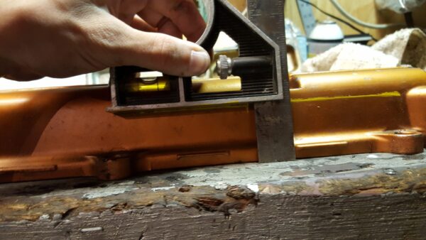
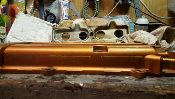
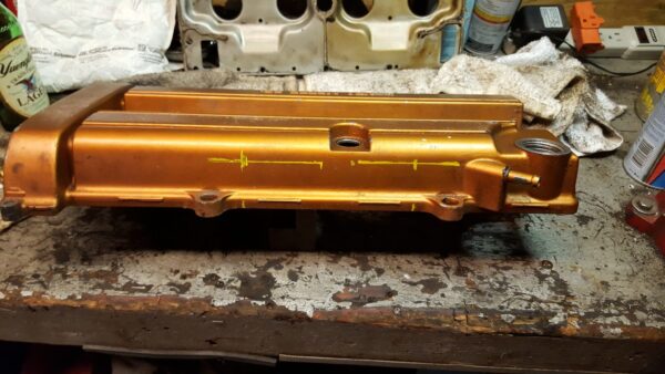
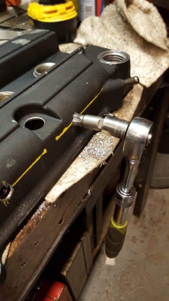
1. To best utilize the existing baffles on valve cover and minimize the oil content in vented gases it is important to locate the ports on the side of valve cover that faces the rear of the car. This is the same side Honda put the original PVC ports on.
Mark a clear location where the port will not interfere with the internal casting in the length direction of the valve cover.
Place the valve cover gasket side down on the bench and mark a line 1.625" from bottom of valve cover.
2. Drill location for ports using multiple drill bits to final hole size of 9/16"
Ensure to drill through both outside of valve cover and internal baffle.
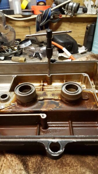
3. Using 3/8" NPT tap. Tap the drilled holes
4. Test fit 3/8" NPT to 1/2" ID hose barbs to ensure threads and taper are deep enough to reach inside of baffled section of valve cover.
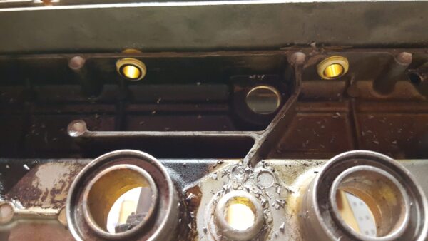
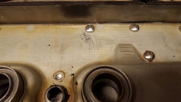
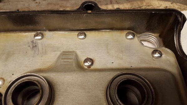
5. Using a 5mm drill, drill all but center located rivet spots(QTY 2 by spark plug tubes Cyl 1 and Cyl 2). Use M6 x 1.0 tap and tap threads into all holes.
Assembly
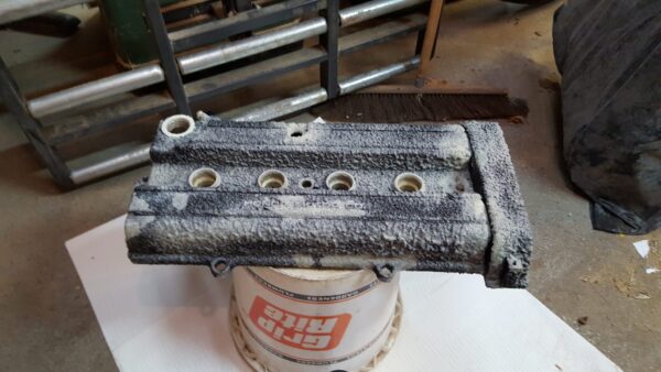
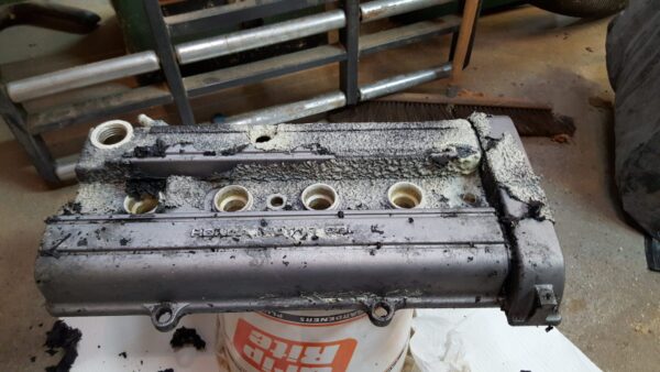
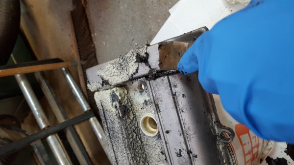
1. Clean all metal shavings from valve cover and baffle. Thoroughly blow out to ensure no metal shavings are left. We chose to paint our valve cover using aircraft paint stripper and VHS "Krinkle" Paint.
2. Place cleaned sheet metal riveted baffle removed earlier. Use Honda Bond or a silicone on originally siliconed locations. Place on valve cover as removed. Attach using M6 x 1.0 x 10mm(long) screws.
Note: Use loctite to ensure screws will not back out and drop into valve train due to engine vibration.
3. Use -10AN or 1/2" ID hose and hose clamp to attach to catch can.
Keep Wrenching !!
