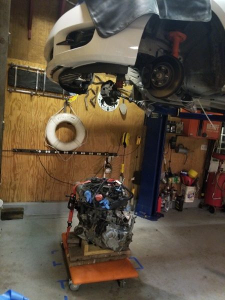
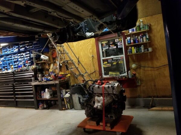
JDM K24A SWAP 8TH GEN CIVIC SI – Part 2: Engine Removal
Getting Started
After sourcing our JDM K24A engine assembly it was time get started wrenching to pull the original K20Z3 out of our FG2 2010 Honda Civic Si Coupe. Pulling an engine is not a short workday evening project, but requires a considerable amount of planning and/or time and tools beyond what fit in the trunk of our FG2 Si. And our all original Si with 223,781 miles was gonna fight us the whole way as any North East USA car does after a quarter million miles.
Beyond an extensive socket set with various extensions and universals, a wrench set including tubing wrenches, the removal of an engine requires heavy lifting equipment.
Engine Pull Vs Engine Drop
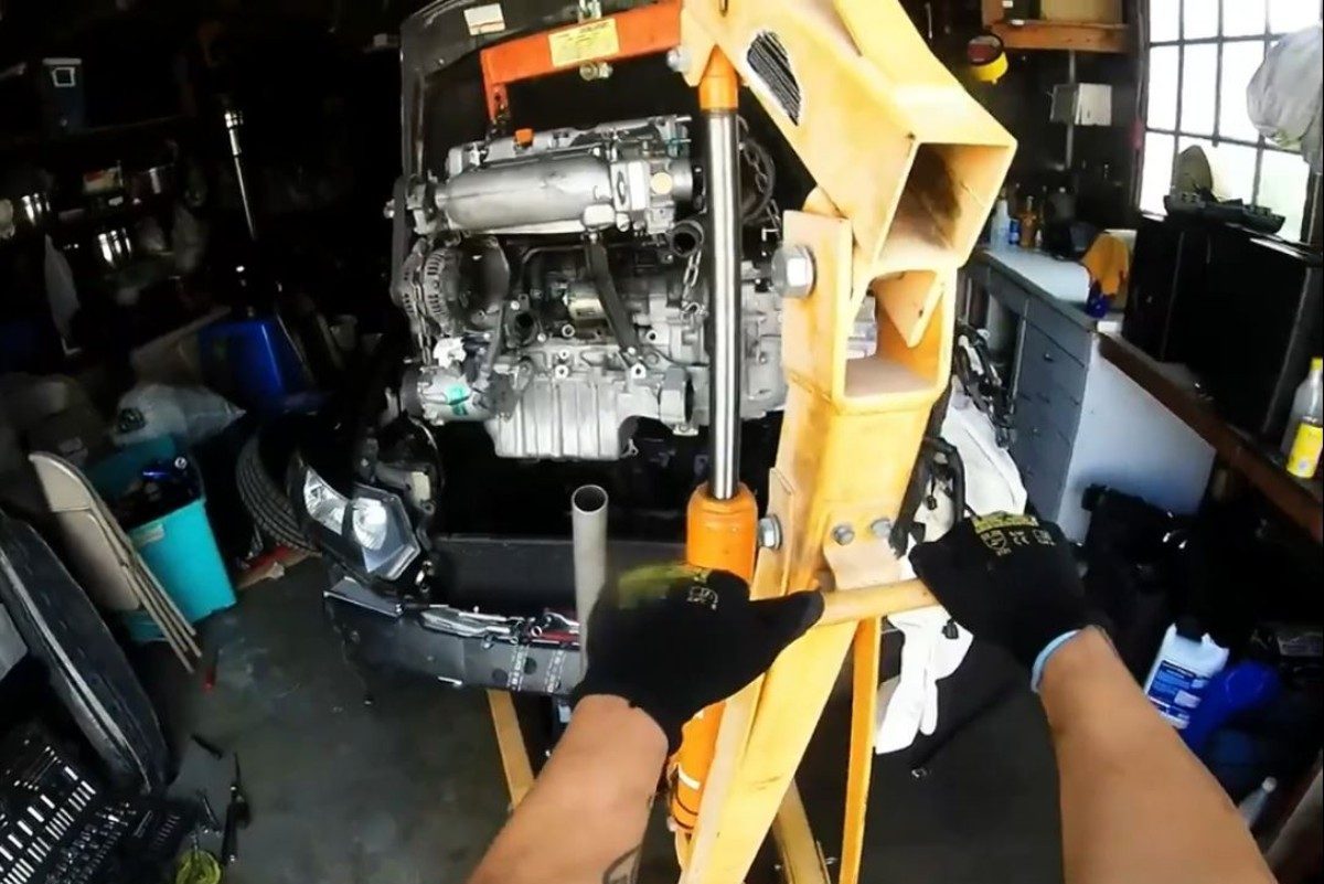
Engine Pull
Engine Drop
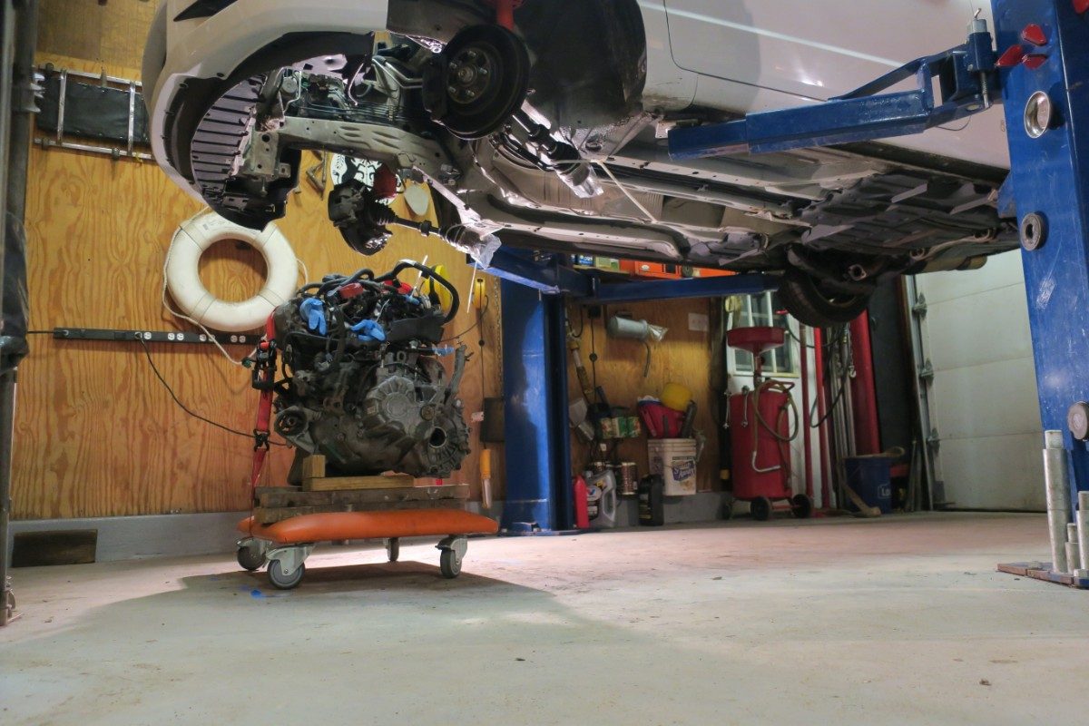
Unlike the 70's, 80's, and 90's Honda chassis, the FG2/FA5 chassis are designed with a lot less consideration for the mechanic. Engine bays are tighter and require a lift to service easily. Engine, transmission, and supporting parts are grouped in larger assemblies for the benefit of factory assembly. However the automotive assembly industry shift to larger modular assemblies allow the engine/trans assembly to come out in larger assemblies than ever before. Vacuum and fuel lines are easier to disconnect ,in usually one location, and the engines require a lot less disconnecting of surrounding parts and brackets to remove from chassis.
However, the implementation of larger modular assemblies comes with a drawback for the DIY Driveway mechanic. The need for a lift. Especially to drop the engine trans assembly out of the car instead of pulling the engine from the top. Despite the Honda Service Manual for the FG2/FA5 2006-2011 Honda Civic specifying the engine should be dropped out, the tight engine bay, and the outstretched A-pillars it is possible to pull the engine/trans assembly up and out of the FG2/FA5 Civic chassis with only a few more steps than dropping the engine out of the bottom using a lift.
For our project we were lucky to have access to a lift to aid in the removal and installation of the engine.
To ease in aligning of engine mounts and clearing components during removal and install, it is highly recommended to remove the subframe as part of the process. This will aid in having enough clearance to drop the motor to remove the transmission mount for engine pull style removal as well as provide clearance to drop the engine out of the bottom.
Subframe HAS to be removed to drop engine/trans out from chassis.
Engine component procedure outlined below is the same weather pulling from top or dropping out of the bottom. Steps written in RED of this procedure are used to identify steps necessary for Engine/trans assembly being pulled from top ONLY.
Check out the time lapse video of the whole process in 5 minutes
Engine Removal Process
Disconnect Engine/Chasis Components
1. Lift vehicle on jack stands or lift
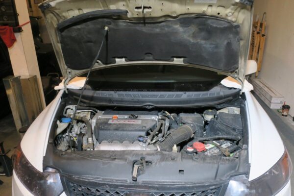
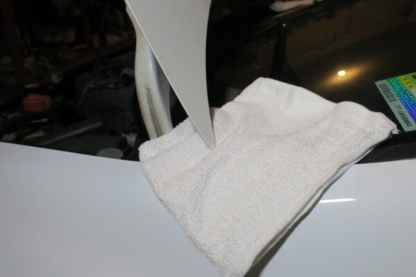
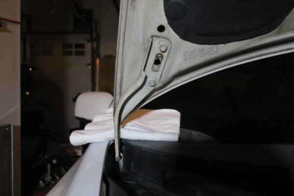
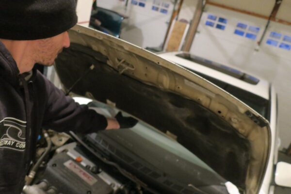
2. Raise Hood. Support with hood prop rod. Place 2 towels on fender where hood is attached to hood hinges.
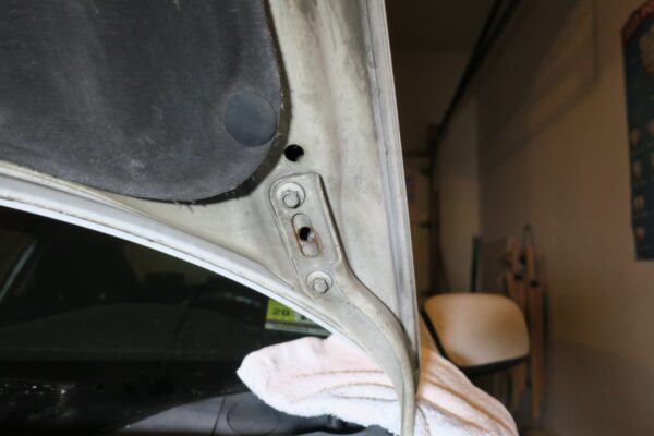
3. Remove QTY 4 bolts attaching hood to hood hinges. Towels ensure hood corners do not scratch fenders.
4. Remove hood
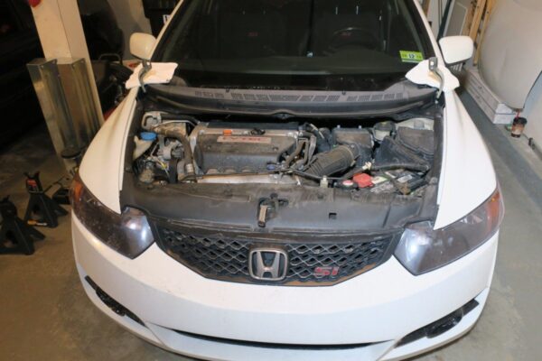
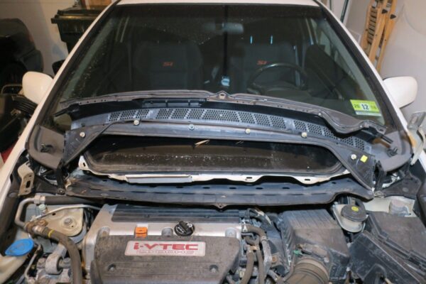
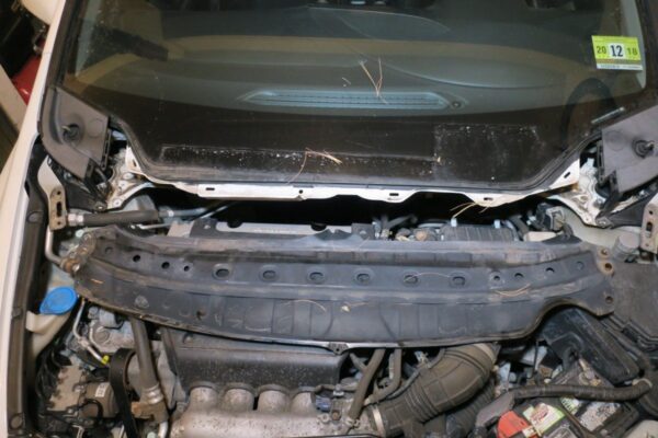
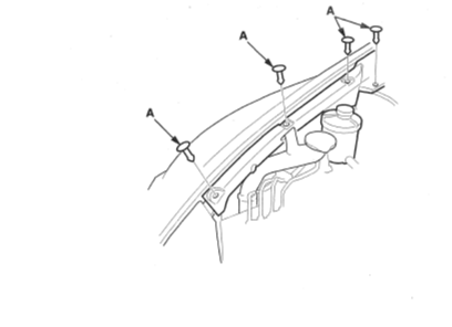
5. Remove QTY 3 pop up clips on front of wiper cowl
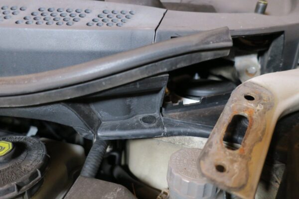
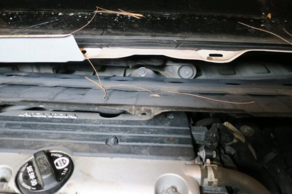
6. Pop up wiper cowl
7. Disconnect windshield sprayer hose on passenger side of cowl
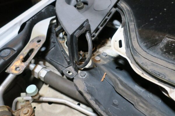
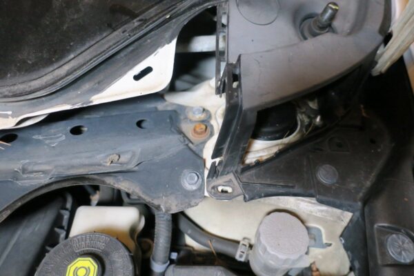
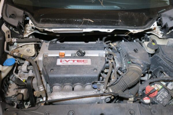
8. Remove QTY 6 bolts on each side of strut brace/lower cowl
9. Remove QTY 3 bolts along the length of the strut brace/lower cowl
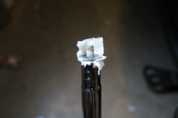
NOTE: Use paper towel between socket and bolt head to keep bolts from falling during removal.
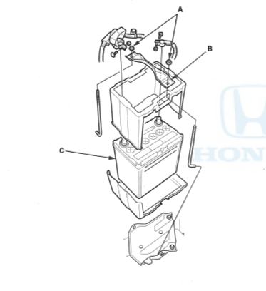
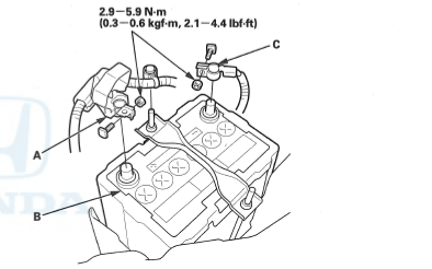
10. Remove negative terminal harness of battery
11. Remove positive terminal harness of battery
12. Loosen both J bolt nuts. Remove bolts and battery tie down
13. Remove battery
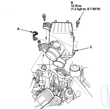
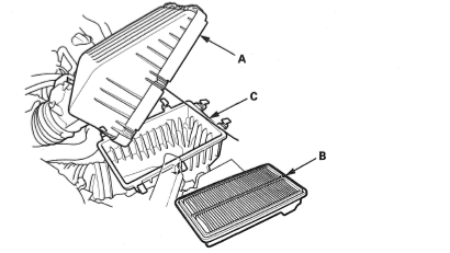
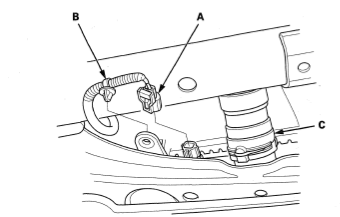
14. Remove intake filter box top by releasing clamps(C)
15. Loosen intake tube to throttle body clamp
16. Disconnect MAF sensor plug(A), remove harness clip from Filter box top
17. Remove intake tube and intake filter box top
18. Remove QTY 3 intake filter lower box bolts(B). Remove box.
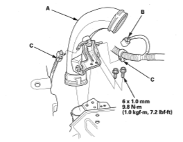
19. Remove intake tube attached to battery tray. Disconnect connector at intake tube.
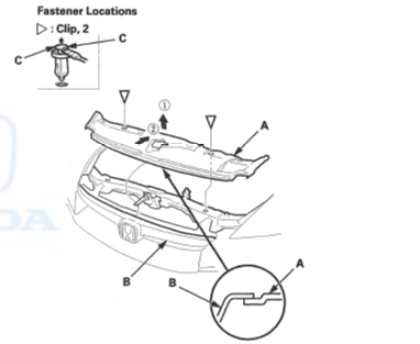
20. Remove Radiator upper support cover by removing 2 pop up clips in center of cover. Remove 2 pop up clips at fenders.
21. Drain all fluids
22. Remove Wheels
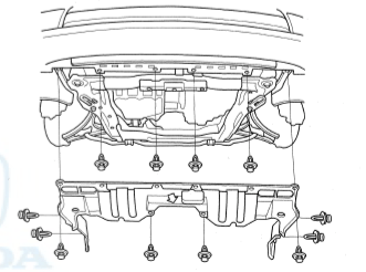
23. Remove Splash shield
24. Disconnect ECT2 sensor (temp sensor in radiator)
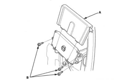
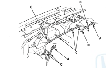
25. Remove ECU plastic cover
26. Remove QTY 3 ECU bolts, tilt ECU forward, away from fender
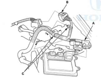
27. Remove ECU connector plugs by pivoting locking tab towards back towards harness.
28. Remove ECU
29. Remove ECU harness at connection by firewall
30. Remove harness from retaining clips on chassis until harness is connected to engine(head) only.
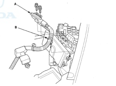
31. Pull cover off fuse box
32. Remove charge harness from fuse box by removing QTY 2 bolts
33. Move charge harness from all chassis mounts
34. Unplug radiator fans from radiator support harness
35. Pop out harness clips from rear of radiator support until harness is not tethered to support.
36. Remove QTY 3 Hood locking mechanism bolts. Remove cable from hood locking mechanism
37. Remove hood cable and retaining clip from radiator support.
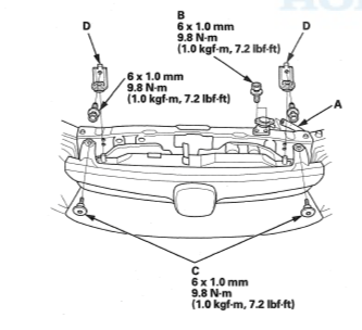
38. Remove QTY 2 Allen head screws retaining front grill from radiator support
39. Remove QTY 2 bolts retaining A/C Condenser from radiator support.
NOTE: It is not necessary to remove upper radiator stay brackets from radiator support.
40. Remove QTY 2 bolts for radiator fill neck
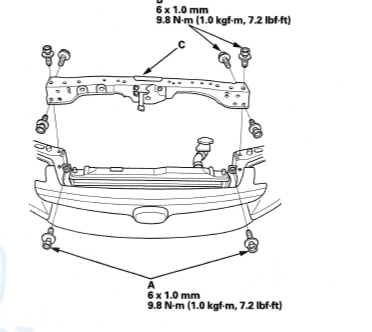
41. Remove QTY 6 bolts from radiator support sides. Remove radiator support.
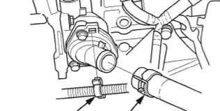
42. Remove upper rad hose from head.
43. Remove lower rad hose from thermostat.
NOTE: Removal of harness from thermostat is not necessary
44. Remove radiator
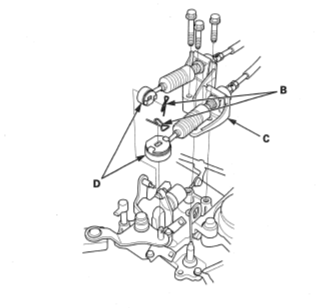
45. Remove shifter cables pin from shift levers on transmission.
46. Remove shifter cables from shift levers
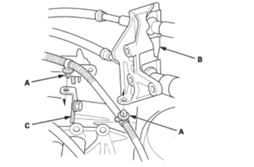
47. Remove shift cable bracket from transmission, QTY 3 bolts
NOTE: 1/4" drive short socket and extension required for some bolts
48. Remove harness clips from from shift cable bracket. Push bracket and cables towards brake master cylinder. Zip tie to secure out of the way.
49. Disconnect the A/C line on passenger strut side using crescent wrenches
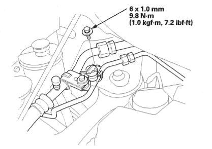
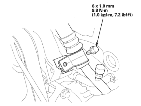
50. Remove A/C line bolt from belt tensioner
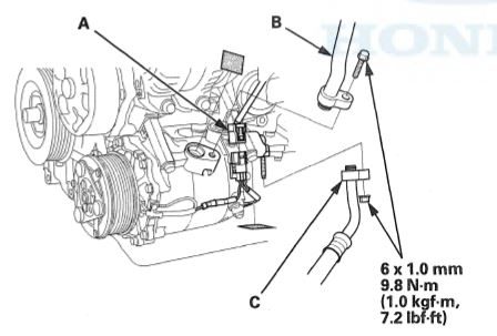
51. Remove A/C lines from compressor. Zip tie small bag to end of hoses and lines.
52. Remove low pressure (larger diameter) A/C line from vehicle
To ease removal of engine trans assembly using pulling method:
*Remove serpentine belt belt*
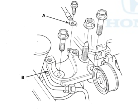
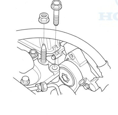
*Remove serpentine idler pulley and bracket*
*Remove QTY 4 A/C compressor Bolts and A/C compressor*
*Disconnect Alternator plug and Charging wire from alternator*
*Remove Alternator*
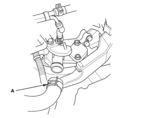
53. Pop off fuel line connection cover
54. Squeeze green tabs on fuel line connection
55. Disconnect fuel line. Un-clip fuel line towards rear of car and move fuel line out of the way
56. Disconnect Evap hose at rear of head
57. Disconnect brake booster hose at rear of head
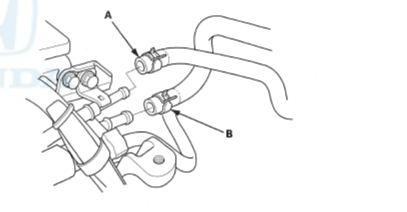
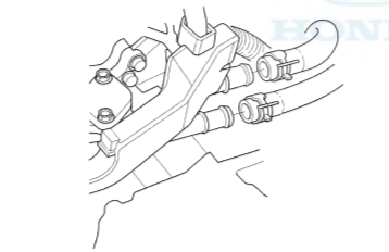
58. Disconnect heater core hoses at rear of head
59. Disconnect Primary oxygen sensor plug at fire wall. Unclip sensor wire from holder
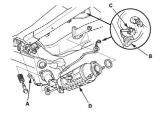
60. Disconnect secondary oxygen sensor by removing plug in exhaust tunnel, reaching inside hole to disconnect sensor plug. Unclip sensor wire from holders
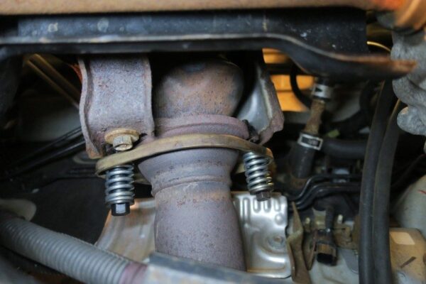
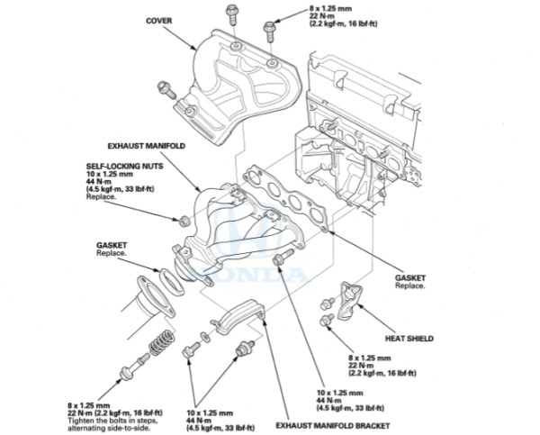
61. Remove exhaust bolts between catalytic converter and header.
NOTE: Use Acetaline Torch or Penetrating oil
62. Remove QTY 3 exhaust nuts at rear of catalytic converter or QTY 2 exhaust bolts at muffler
NOTE: Use Acetaline Torch or Penetrating oil
63. Remove exhaust hangers holding up section
64. Remove catalytic converter and exhaust mid pipe (if applicable)
* Remove Exhaust manifold (header) to ease removal of engine/trans from top*
Subframe Removal
Removing the sub frame greatly increases the ability to maneuver engine/trans assembly when pulling out from the top of the car. The whole transmission mount must be removed from chassis to pull engine/trans from the top. Lower transmission mount bolt is tight against trans, using a wrench is necessary, short socket with universal with extension may be possible. Its is completely necessary if removing the engine/trans assembly from the bottom. Removal is simple, but not necessary if pulling engine/trans from the top. Removing sub frame allows axles to not be unbolted from knuckle assembly.
If Pulling the engine/trans up and out, ensure enough space is in front of car for engine/trans hoist to operate. Once subframe is removed, car chassis can not be put back on front wheels.
To Remove Subframe:
1. Remove tie rod from knuckle
2. Loosen QTY 4 sway bar mounting bolts
3. Remove QTY 2 nuts and QTY 1 bolt from each lower control arm securing the ball joint
4. Using pry bar pry lower control arm from ball joint past the ball joint studs
5. Remove EPS Rack Plugs
6. Loosen QTY 4 lower Subframe bolts
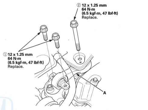
7. Remove lower torque mount Bolts
8. Remove front torque mount Bolt
9. Remove lower torque mount by rocking the engine till it is able to be removed
10. Remove under dash cover and column cover
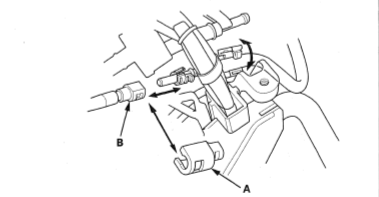
11. Disconnect rack from steering column universal. Support column telescope section with large zip tie or string
12. Support subframe with jack stands. Remove QTY 6 Subframe bolts (2 on side)
13.Remove QTY 6 Subframe bolts (2 on side)
13. Lower subframe or raise chassis
Check out our Time lapse video of the whole removal process from our Youtube Chanel.
Final Steps and Engine/Trans Removal
If sub frame was not removed. Axles Removal Procedure:
- Remove 36 mm axle nuts
- Remove front caliper bracket from strut
- Remove ABS wire from strut
- Remove QTY 2 bolts securing top of knuckle to strut
- Pop out axle using pry bar from trans/half shaft
- Pull knuckle away from car and remove driveshaft
Subframe Removed Axle Disconnect Procedure:
- Remove ABS wire from strut
- Pop out axle using pry bar from trans/half shaft
- Rotate knuckle and driveshaft so driveshafts face rear of the chassis
- Secure to chassis using string or large zip ties
If Replacing clutch slave cylinder:
1. Remove Clutch fluid from Clutch reservoir
NOTE: Turkey Baster works great to suck out fluid. DO NOT get brake/clutch fluid on paint
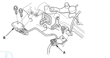
2. Disconnect clutch slave cylinder line using 10mm tubing wrench. Tie bag with zip tie at end of line.
3. Remove clutch line and clutch line bracket from transmission. Set clutch line to side.
NOTE: Remove clutch slave cylinder to prevent from dripping during engine/trans removal
If NOT replacing clutch slave cylinder:
1. Remove clutch line bracket from transmission.
2. Remove QTY 2 bolts from clutch slave cylinder. Move slave cylinder and secure clear of engine/trans, tie to radiator lower support frame
Engine/Trans Removal from Top
- Remove battery tray from chassis. Secure and tuck away any chassis harnesses and clutch line
- Remove front torque mount
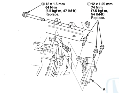
3. Attach engine leveler to:
- Eyelet at center or rearward on transmission
- Top bolt of serpentine idler bracket(removed previously)
4. Attach engine hoist to leveler
5. Raise hoist till engine/trans weight is removed from mounts
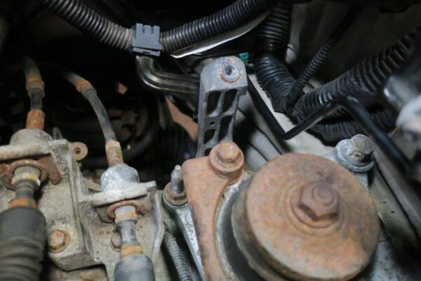
6. Remove transmission mount
- Remove ground cable
- Remove QTY 2 nuts and QTY 1 bolt securing trans to mount
- Lower engine/transmission 2"
- Remove QTY 3 bolts securing mount to chassis
- Remove transmission mount
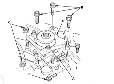
7. Raise engine/transmission 2"
8. Remove engine side mount
- Remove upper torque mount
- Remove QTY 1 bolt securing engine side mount aluminum top to engine side mount
9. Raise engine/trans assembly slowly
- Verify engine/trans assembly is free of snaging
- slowly lift and move assembly towards front of car to not damage windshield
- Lift and observe frequently till assembly is clear of chassis.
Check out CAMMEDCivic's YouTube video, showing the engine/trans assembly being pulled out of the 8 gen Civic Si fg2/fa5 chassis.
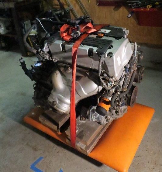
10. Once removed, lower onto dolly
- Use wood blocks to ensure engine/trans is sitting flat on dolly
- Secure using ratchet strap
Engine/Trans Removal from Bottom
- Support Engine/Trans Assembly on Dolly or jackstands
- Use wood blocks to ensure engine/trans is sitting flat on dolly or stands
- Use ratchet strap to secure engine/trans to dolly
- Remove QTY 2 nuts and QTY 1 bolt securing transmission to transmission mount
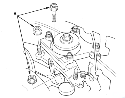
4. Remove QTY 1 nut and QTY 1 bolt from engine side mount securing to engine to mount
5. Raise chassis slowly
- Verify engine/trans assembly is free of all components as you lift
- Lift and observe frequently until chassis is free of engine/trans assembly
6. Remove engine from under chassis
Check out Driveway Built (Our) YouTube video, showing the engine/trans assembly being dropped out of the 8 gen Civic Si fg2/fa5 chassis.
Now that engine/Trans is out we can seperate trans from engine on dolly:
- Use dolly and 2x4 on edge under oil pan to support assembly so trans is not touching dolly. Oil pan should be supported
- Remove all trans/engine mounting bolts
NOTE: rear starter bolt does not need to be removed - Remove dust shield
- Remove Transmission
Keep Wrenching !!!
